

Enbridge's Intelligent Valve Placement (IVP): Illustrations
ENGLISH | FRANÇAIS
Isolation valves are used to control or halt the flow of crude oil and other liquids, and represent an invaluable piece of safety equipment on a pipeline system.
Enbridge's Number 1 priority, as a company, is the safety of the public and the environment, and the operational reliability of our pipeline systems. Enbridge's Intelligent Valve Placement (IVP) program is a key component of our commitment to safety and operational reliability.
Enbridge's IVP methodology is designed to ensure the right valves are placed at the right location, to reduce potential release volumes along a pipeline corridor. Using thorough engineering practices and exhaustive risk assessment, our IVP program takes such a rigorous approach to valve placement that it considers and protects water crossings, as well as other high-consequence areas (HCAs), from potential impacts to people and the environment.
Double Sided Valley
2 Valves Installed
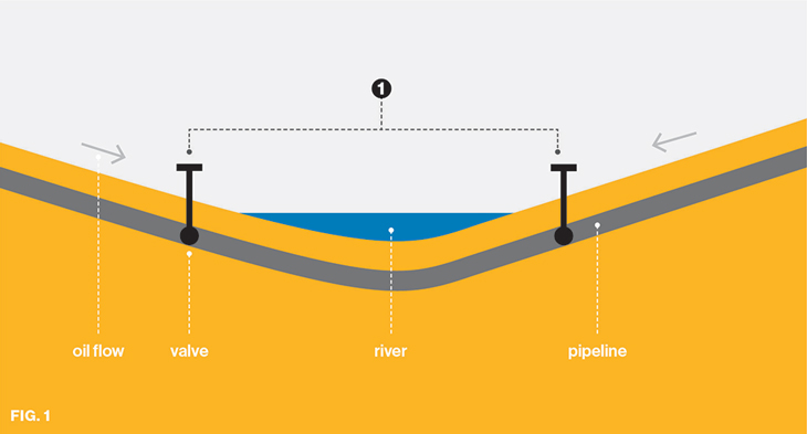
Oil flows downhill in a pipeline after the system is shut down. In a valley scenario as depicted, Enbridge installs an isolation valve on each side of the water body.1 The specific valve locations (including distance from the water body) are optimized through the IVP methodology.
Single Sided Valley
1 Valve Installed
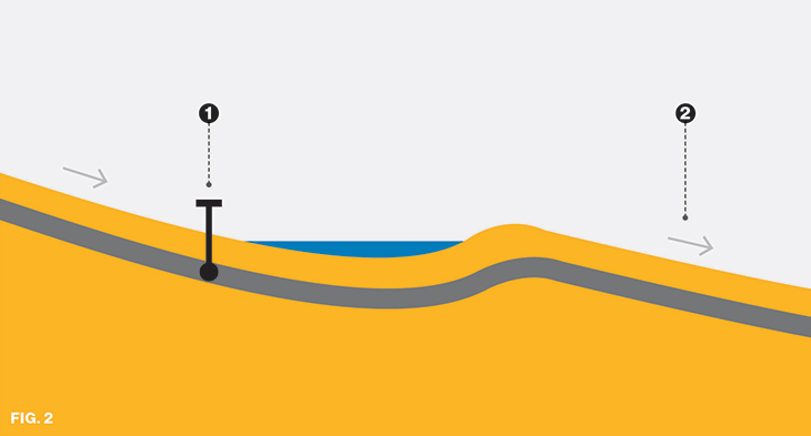
In this scenario, an isolation valve is placed on the left side of the body of water.1 However, on the right side of the body of water,2 oil would drain downhill away from the body of water, and a valve would provide no isolation benefit. A valve would be more optimally placed downstream, closer to any water bodies or HCAs.
No Valleys
Liquid Remains in Place Naturally

In some cases, bodies of water are at high points along the line. In the event of a release, these areas would act as natural isolation points due to gravity; oil would not be able to flow uphill into the body of water therefore no isolation valves are employed.1
Flat Landscape
Liquid Remains in Place Naturally
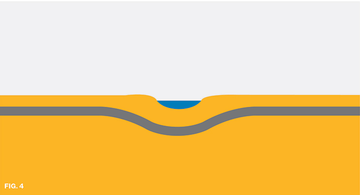
Pipeline terrain tends to be flat by design (a 70-kilometre stretch of Line 9, for example, crosses through territory with little change in elevation). In the event of a release, oil would stop flowing within the line and remain confined to the immediate area of the release. Valves provide no additional isolation benefit.
Long Valley vs. Short Valley
Ideal Placement
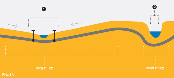
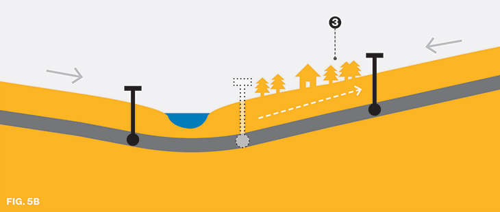
In the event of a release near a body of water at low elevation, longer valleys mean larger potential release volume; in this case, isolation valves on either side of the water crossing, in close proximity to the crossing, would be optimal.1 Conversely, in a short, steep valley, valves often cannot be installed close to the body of water, due to the steep slope of the bank as well as the possibility of flooding; and in the event of a release, valves would only help limit oil drain along the short length of the bank, and provide little isolation benefit.2
In some cases (Fig. 5B), isolation valves are not directly adjacent to the banks of major water crossings. Instead, they are intentionally placed to protect not only major water crossings but also high consequence areas such as additional watercourses, water intakes, urban infrastructure, and ecologically sensitive areas 3 – and exceed regulatory requirements in doing so.
Long Valley - Multiple Crossings
Ideal Placement
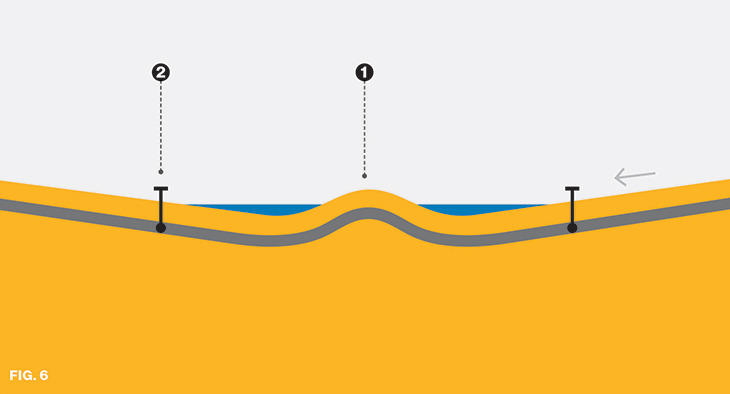
For a long valley with multiple water crossings, the land between the crossings acts as a high point, providing natural isolation from crossing to crossing 1. Optimal valve location at left is near the bottom of the long, sloping valley;2 this placement, in effect, allows one valve to protect more than one water crossing.
Line 9
Example of Intelligent Valve Principles (Cardinal Station to 3543.1)

From Cardinal Station 1 downstream by approximately 40 kilometres, pipeline elevation slopes generally downward to the east. This long section contains no water crossings, and has elevation features that naturally protect the HCAs in this segment. A large hill,2 acts as a natural isolation point for terrain to the east. In the event of a rupture 3 only the cross-hatched area of the pipe 4 would be released, about 950 m3. The rest of the product west of the hill would remain in the pipeline due to the isolation from the hill, even though the closest upstream valve is over 40 km away.
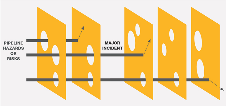
Enbridge Risk Management Program
Valve Placement is one of multiple layers of defense provided through the Enbridge Risk Management Program to protect people and the environment from potential risks associated with our pipelines.
Inherently Safer Design and Construction
- Design Standards
- Material Selection
- Construction Inspection
- Safety Culture Prevention
- Third Party Damage
Prevention
- Pipeline Integrity Management
- In-line Inspection
- Control Centre Operations and Procedures
Detection
- Leak Detection
Control and Mitigation
- Valve Placement
- Pipeline Monitoring
Emergency Response
- Emergency Response


